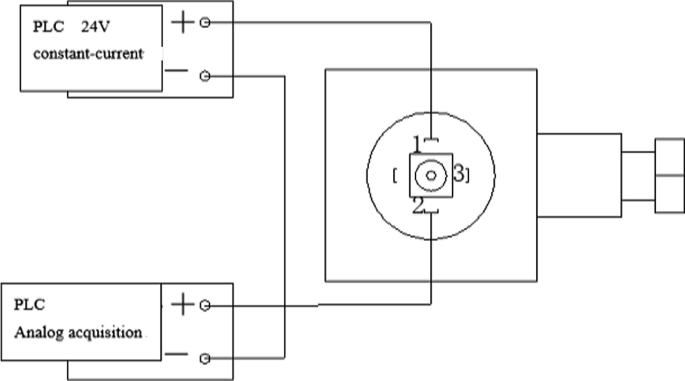
uvc-24v wiring diagram
A typical germicidal ultraviolet light for heating and cooling systems produces about 90 percent of its energy in the UV-C wavelength. Hot Product 12V DC Power Supply UV Ballast for 4-8W PL15-180-10D12.

Shelly 1 Shelly Cloud
Quattro-II 5kW-24V-230V AC 460Ah AGM Cerbo GX touch 50 MPPT Generator.

. UV-Aire Induct Air Purifier Systems. Its easier to read the steps by comparing them to the 24v trolling motor wiring diagram listed above. Slightly pull on the wire to ensure it is locked into the terminal.
To remove a wire from. It is installed in the main supply or return duct and operates continuously to automatically purify the air in the home 24 hours a day. REME HALO UV Light Air Purifier Model REME-H-24 Wiring Diagram IMPORTANT NOTICE.
12 UVC Single Lamp 120V wangle bkt. Any advanced configurations should be. Install male and female con-nector to remote door.
16 UVCPCO Air Purifier 24v 120v. AC DC System for vehicles. 16 UVC 120V In-Duct w.
Connect the positive terminal of battery A and the negative - terminal of. Wiring diagram for a VEBus panel. 12V DC Power Supply UV Ballast.
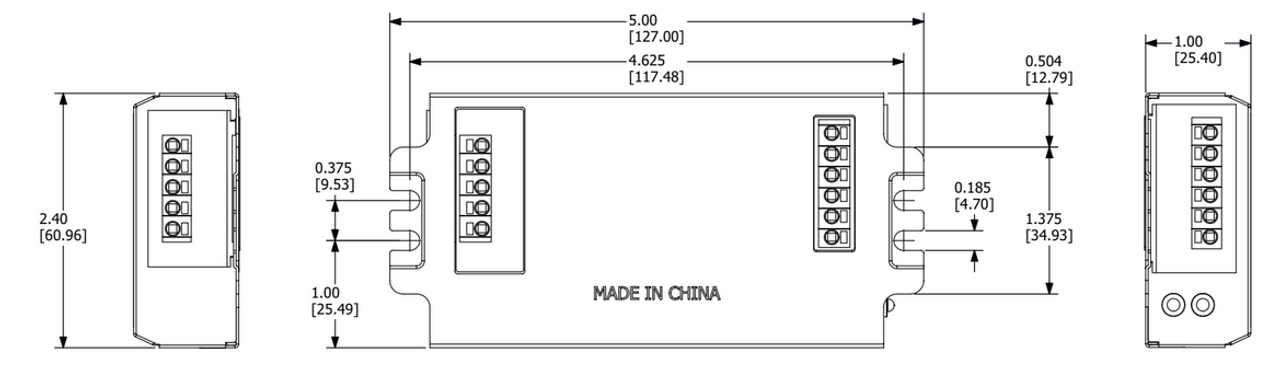
VEBus BMS example with 3kW 12V MultiPlus. RGF recommends for Optimal Performance and Maximum Cell life product operates. Find a suitable cool dry location for the ballast making sure supply cord to ballast will reach 24 volt power supply and that lamp connector can reach the desired lamp mount area.
Air Conditioner Thermostat Wiring Details and Color Code R Terminal is Connected to the Red Wire or R Wire - this is 24-volt power for the thermostat and controlled devices. More complex installations are supported but correct wiring may depend on deployment-specific characteristics not covered in these diagrams. About four percent of its energy is given.
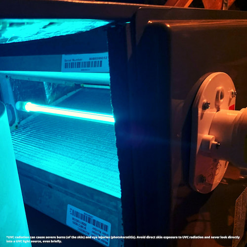
Specifications Product Overview Healthy Climate UVC Germicidal Lights Eliminate pollutants from indoor air Germicidal lights use intense rays of ultraviolet light to control and kill. Use the wiring diagrams below to connect to power. 11 14 UVCPCO Air Purifier 24v.
The UV-1624V lamp UV whole house air purifier requires. When you make use of your finger or even. Secure wire with strain relief that is provided with the door interlock switch kit.
Audio Wiring Diagram 1. Insert a stripped wire into the corresponding hole of the terminal block. The low voltage power supply 18 to 32 VAC is marked ER.
The high voltage 120 to 277 VAC power supply is marked ST. Insert remote door interlock switch wire through hole.
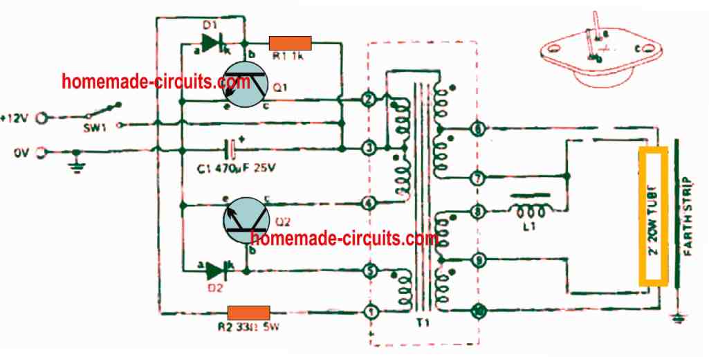
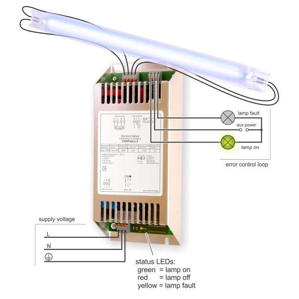
Electronic Ballast Circuit For Uv Germicidal Lamps Homemade Circuit Projects

Control Transformer 40va Primary 120 208 240v Secondary 24v Hvac Furnace Multi Tap Amazon Com

G350 24v Uv Light Air Purifier For Ac Hvac Coil 14 Bulb Ebay

8s 24v Waterproof 15a Bms Lithium Lipo Lifepo4 Electric Scooter For Lithium Battery
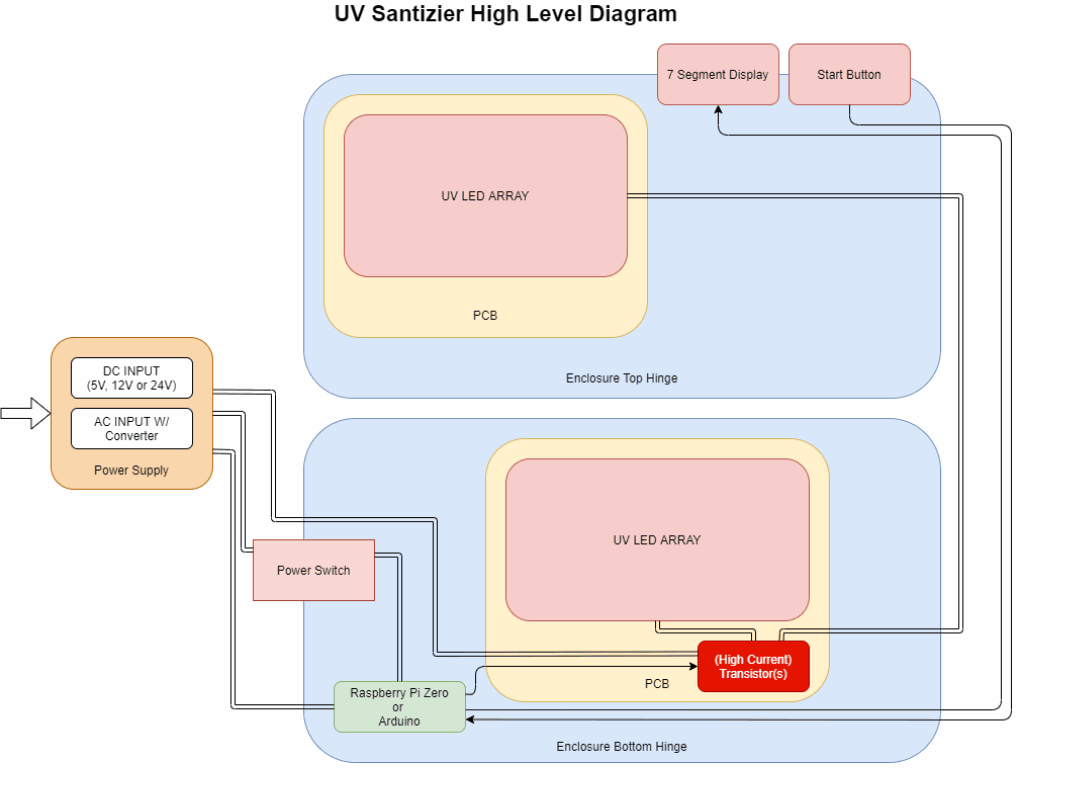
Designing And Building A Uv Sanitizer

Atlantic Uv 10 0400 Ballast 23 25v Ac Dc 15 50w Includes Specification Sheet Wiring Diagram Prolampsales
E80is

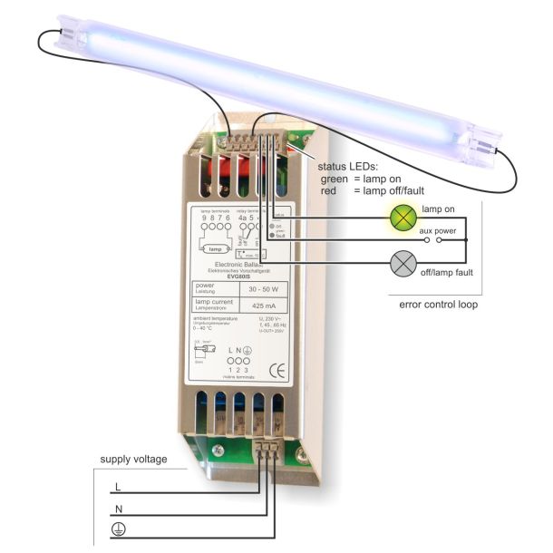
Schematic Diagram Of The Uvc Fluorescent Light Circuit Installed In The Download Scientific Diagram
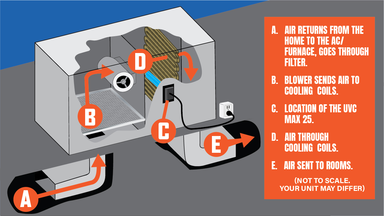
Uvc Max 25 Installation Guide Air Care
Robertson Psm1gph18dw24 Germicidal Ballast
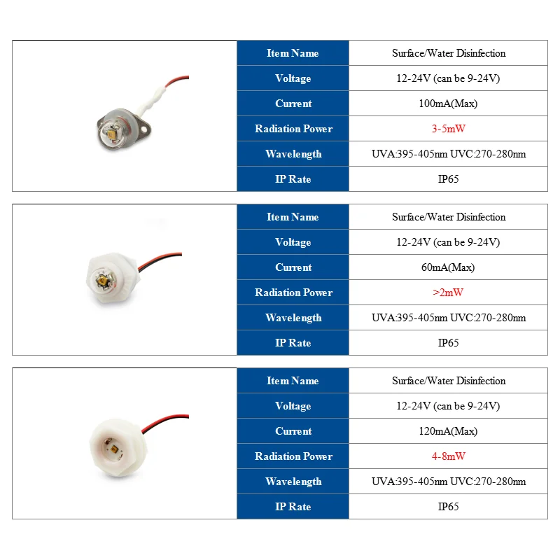
Uv Lampe Perlen Uvc Led Uv Licht 395nm 280nm 12v 24v Antiseptische Uv Sterilisator Fur Wasser Reinigung Oberflache Desinfektion Leuchtperlen Aliexpress
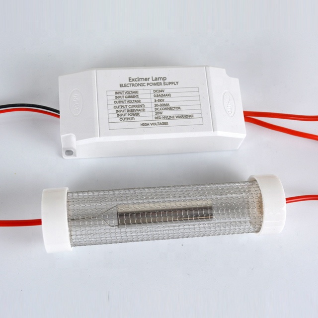
Quantalamp 20 Watt Far Uvc Excimer Bulb 222nm Far Uvc F Series 20w Far Uv Light 24v Dc Quantadose Far Uv Uvc Light And Detection
Uv 16 24v Induct Uv Air Purifier For Home Field Controls
Development Of Control System For Ballast Water Management System Springerlink
E400ph S

Simple Converter To Power Uv Lamp Power Supply Circuits

Shelly 2 5 Shelly Cloud